Monitoring
Environment, building equipment, industrial sites and ITsystems, as well as utilities, need to monitor their environment and operational conditions reliably and efficiently. An overview of selected variables such as temperature, pressure, dew point, lighting level, air quality, machine operation or vibration, provide a comprehensive picture of the state of the equipment and enable the operator to respond appropriately.
Monitoring teploty ve zdravotnictví
Product canceled
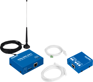
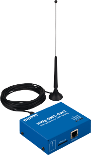
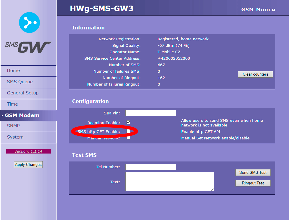
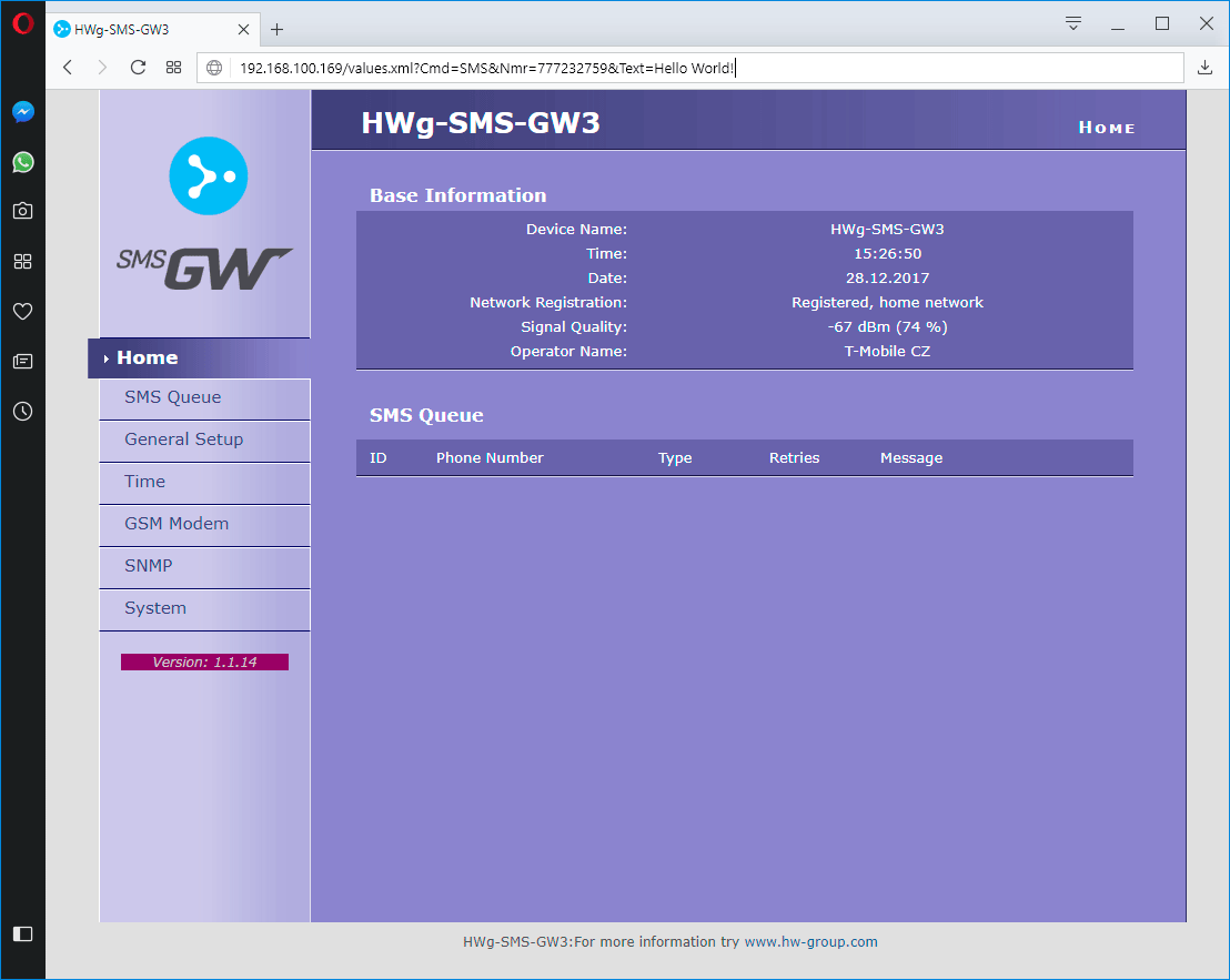
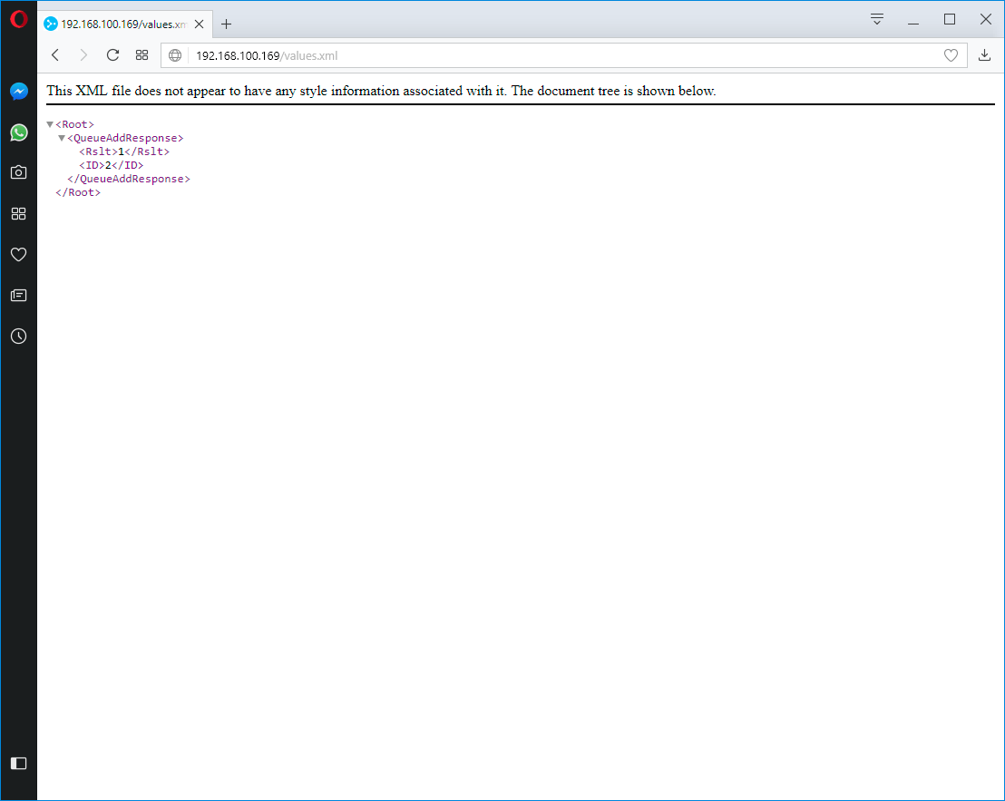
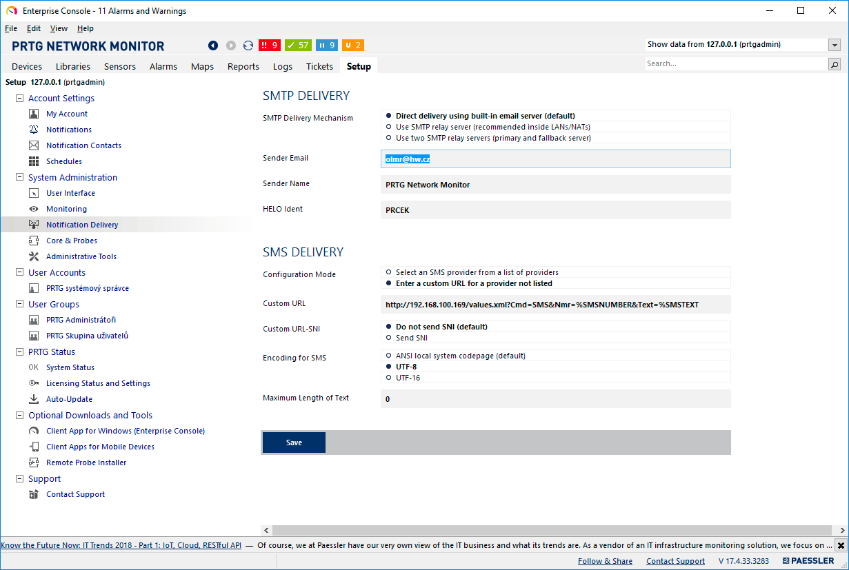
How to send SMS via HWg-SMS-GW3
HWg-SMS-GW3 is a SMS gateway for sending text message alarms over a LAN. HWg-SMS-GW3 is primarily intended for use with HW group products and software. However, its communication interfaces are sufficiently documented for use with third-party systems. This Application Note shows how to use HWg-SMS-GW3 in such third-party systems.
Horizontal menu
Accessories
Download
Selecting M-BUS communication type (displaying multiple values from a meter)
The M-BUS is designed for low consumption, and for this reason allows to query device values using different requests. The issue is that some meters respond to a “Basic” request only with the total consumption values; another request type (REQ_UD1, SND_OUD or other) must be used to display more readings, such as the immediate consumption, flow, etc. To this end, HWg-PWR allows to add another meter with the same secondary address. A hidden option is used to activate these advanced request settings.
Horizontal menu
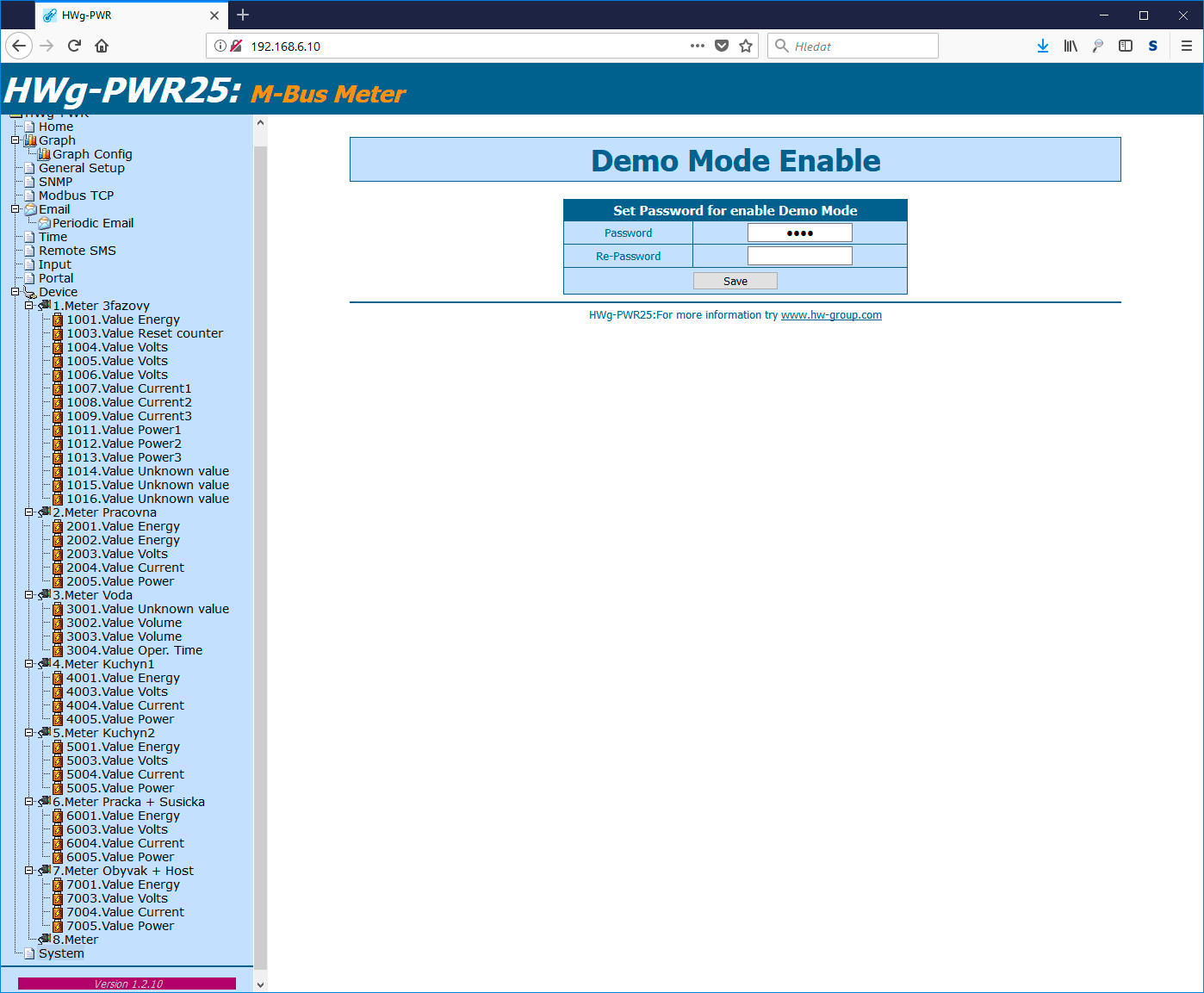
The hidden option is activated on the System page of the HWg-PWRx:
In the Password field (first line only), enter #Hwg
This activates the Secret Setup:
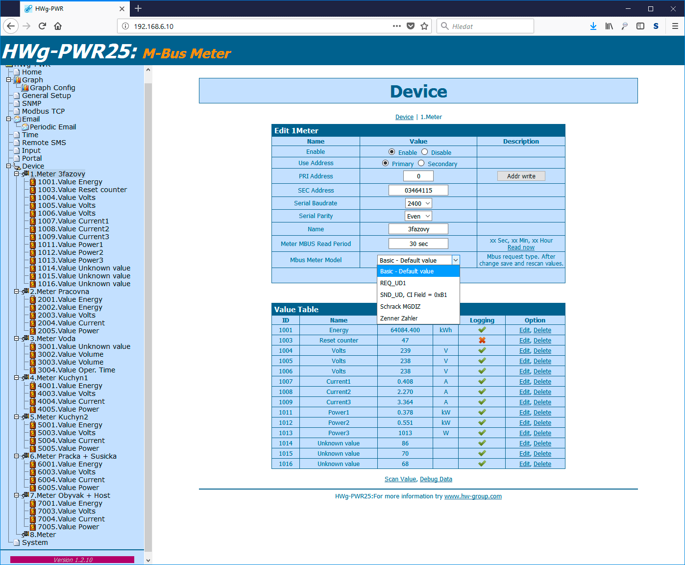
Here, enable the Mbus Meter Model Enable function. Then, switch to the page for the particular meter. The following item is displayed:
Select and save to activate the corresponding mode.
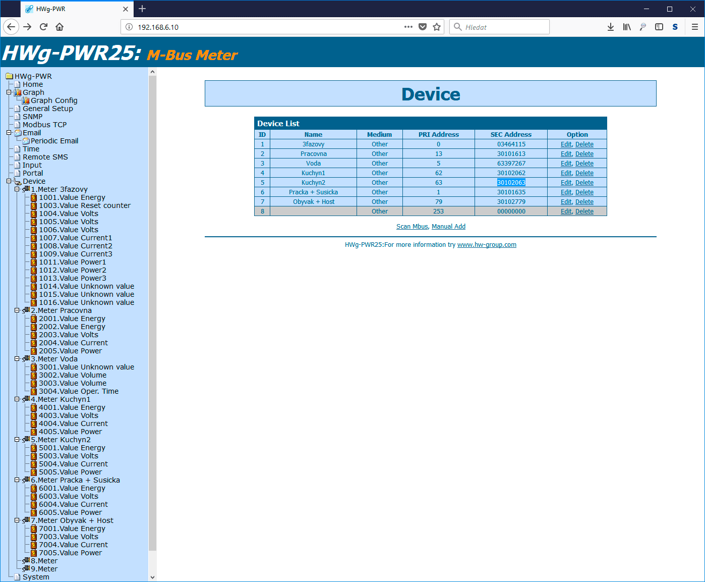
In order to read the values with different requests, the particular meter needs to be manually added to HWg-PWR once more. At the Device page, copy the SEC address of the meter:
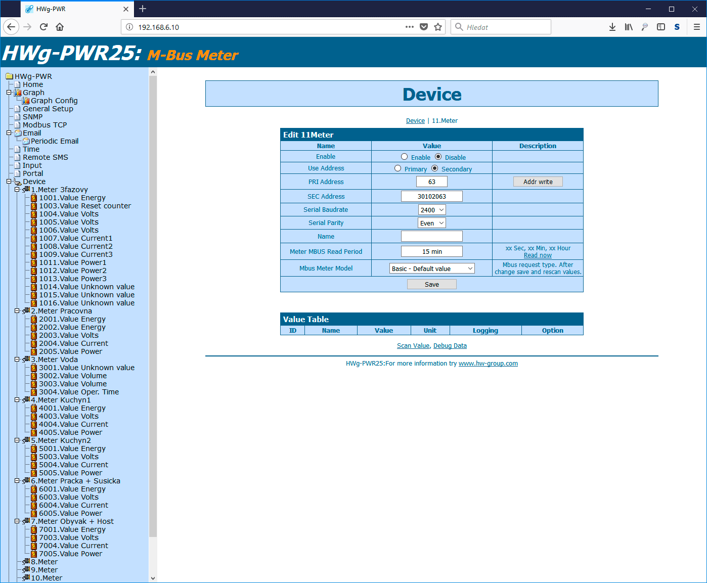
Then, click the Manual Add link at the same page. A dialog for adding a device manually appears. Enter the meter’s secondary address and select it for use for the reading.
After saving the changes, continue with the automatic finding of values as usual.
Virtual outputs in Poseidon2/Damocles2
Virtual outputs in Poseidon2 and Damocles2 units allows to use outputs from different Poseidon2 and Damocles2 units (Box2Box). De facto we are talking about similar feature, which was based on SNMP traps, only in case of Virtual outputs the communication runs more reliable way via TCP/IP protocol, it is repeated (done each 60s), secured and all functions work this way too, conditions and features same as with physical outputs.
Horizontal menu
Reliable protocol
Existing features of SNMP traps meant trasfer via UDP protocol, which is not confirmed, in other words the side which sent a trap, does not know whether it was recieved by target device. The UDP packets are very fast and short, however there might be losses, which is not suitable for Box2Box use. TCP protocol on the other hand has all packets confirmed, so when data are not recieved, the source device is prompted to resend it again.
Repeated each 60s
When using Box2Box mode via SNMP Traps, commands for switching on and off are always sent only at the moment when a condition for sending an alarm trap is met (start or end of an alarm). When you have an application which allows you to reset the remote device (e.g. due to power outage) with controlled output, this transmission is not suitable, because after restart (power on), the remote device doesn‘t know that it has to switch the output. In the case of Virtual outputs an instruction is sent each 60s for as long as a condition switching remote output remains valid. The problem is solved.
Secure communication
In remote equipment, communication for virtual outputs can be secured by a username and password (level Read only + Outputs or Read + Write). SNMP Traps do not have this feature.
You can apply the same functions to Virutal Outputs as to physical ones
After adding a virtual output to unit Poseidon2 or Damocles2, this output will be displayed in the same tab with the same parameters as for the physical output. All conditions can be applied and atributes as for the physical one, including the option of creating pulse output.
How it all works
First we define on the Virtual Outputs tab virtual output. Normaly there can be up to 8 and they are off in default mode. After enabling, the following can be configured: the name, the IP address of the remote device, ID remote output (can be found in the Outputs tab); if the device is secured by authentication, we can set a username and password (levels Read only + Outputs or Read + Write).
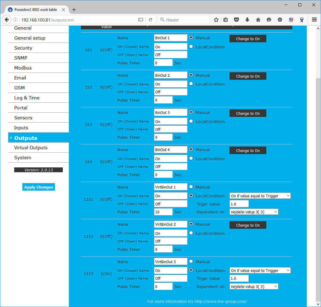
After save we can see the output on tab Outputs and we can configure it as we need
Reaction time for switching the remote output is around 1,5-2,5s.
Download
MQTT in practice on Poseidon2/Damocles2
MQTT is a lightweight TCP/IP protocol designed for use in IoT applications or in situations where many external devices send data to a central hub. The central hub can aggregate data and further distribute them to all subscribed devices.
This Application Note describes how to use the MQTT protocol together with broker.mqttdashboard.com and the TT3 application.
Horizontal menu
How MQTT works
MQTT works at the TCP layer in a way similar to SNMP Traps. There is no request-response communication; instead, data are sent ("published") and acknowledged. This reduces network load: individual “input” devices (sensors, detectors etc.) actively send only short TCP messages to a specified address (to a “broker”).
The advantage is that the input devices only transmit whenever they need to – in regular intervals, or according to other manufacturer-specified criteria (input closed or open, a threshold exceeded, a value increase or decrease, etc.).
Each message begins with a “Topic” that identifies, characterizes or groups the data.
Broker
A MQTT broker primarily acts as a server, that is, it receives and stores data. However, it can also act as a client (input device) towards other brokers and forward data to all subscribed subscribers. Such a subscriber can be, for example, a web service, an application, or another broker.
End devices send data to specified broker addresses, subscribers subscribe to brokers (just like customers sign up to receive e-mail newsletters). When a broker receives a message with a Topic corresponding to a subscription, the message is stored and distributed to the subscribers.
Topic
The MQTT topic is always a text string. The slash (/) sign can be used to form a tree structure. The topic can look like this:
Poseidon/1-Wire/temperature/856275
GTS/nagano/room1/temperature
A subscriber can subscribe to a particular topic, to a tree branch, or to the entire tree.
The following wildcard characters can be used in the topic: “#”, “+” and “$”.
- “+” stands for a whole level (Poseidon/+/temperature/856275).
- “#” stands for several levels (Poseidon/#);
„#“ can only be used at the end of the string. - Topics that begin with a “$” (dollar sign) are special – usually system topics.
- When a topic begins with “$”, it is a special topic (such as $SYS/broker/uptime).
The Topic also includes a QoS flag that specifies whether the message must be delivered. 0 means that successful delivery is not required; 1 allows duplicate delivery (if there is no acknowledgement, the message is resent); and 2 indicates that successful delivery is required but without any duplicity.
Payload
MQTT payload is the actual message content. The message content is normally assumed to be textual. However, the MQTT protocol is not restrictive and it is up to the broker and the subscribers to handle the payload. So, the payload can be binary, or can consist e.g. of images. Message size and type are specified by the broker. Many brokers prefer XML or JSON because these formats are less resource-consuming for larger volumes of data than many short “topic” messages.
Security
By default, the MQTT protocol communicates via TCP at port 1883. Security can be enhanced with SSL/TLS; in this case, the communication takes place at port 8883.
MQTT in Poseidon2 and Damocles2
Poseidon2 and Damocles2 units include a MQTT client implementation with optional SSL support.
- MQTT enable – Enables or disables MQTT support in Poseidon2 and Damocles2 devices.
- Server – IP address or domain name of the MQTT broker (server).
- Port – TCP port where the broker listens.
- Username – Username for authenticating TCP communication.
- Password – Password for authenticating TCP communication.
- Secure SSL mode – Enables/disables SSL mode.
- Client ID – ID of the client for use in MQTT. Users enter their IDs themselves in their profile. A user can use multiple IDs in order to filter messages in their account.
- Publish Period – Period for transmitting measured data. In this the interval (in seconds) Poseidon2 periodically connects to the broker to transmit the values.
- Topic Prefix Name – Topic prefix. The entire Topic is then formed by concatenating the prefix + the topic below.
- Publish – Selects information to be sent.
- User Topic umožňuje vytvoření uživatelského topicu (zprávy) obsahujícího data jaké požaduje uživatelská aplikace (JSON, XML, CSV a pod.). K tomu slouží makropříkazy uvedené níže
- User Topic Enable – zapne zasílání uživatelské zprávy
- Topic Name - Název zprávy
- Topic Value – šablona uživatelské zprávy
- Topic Test – náhled výsledné zprávy po přeložení maker
Macros for User topic:
%ID_IN_*% - Start of sequence of the inputs with firmly defined ID’s %ID_IN_END% - End of the fixed sequence of the inputs
%LOOP_IN% - Beginning of the sequence of the inputs that passes all ID’s %LOOP_IN_END% - End of the complete sequence of the inputs
%ID_OUT_*% - Start sequence of the outputs with firmly defined ID’s %ID_OUT_END% - End of fixed sequence of the outputs
%LOOP_OUT% - Start sequence outputs that passes all ID’s
%LOOP_OUT_END% - End of the complete sequence of the outputs
%ID_SENSOR_*% - Start sequence with sensors firmly defined ID’s %ID_SENSOR_END% - End of fixed sequence sensors
%LOOP_SENSOR% - Start sequence of sensors that passes all ID’s %LOOP_SENSOR_END% - End of the complete sequence of sensors
%VAL_ID% - Variable ID item
%VAL_NAME% variable name item
%VAL_VALUE% - variable values of the item
%VAL_STATE% - state variables of the item
Username and password are optional. For example, broker.mqttdashboard.com does not require them yet.
MQTT in practice
There are many public MQTT brokers where data can be sent and topics can be subscribed to. A list of the most well-known ones is available at: https://github.com/mqtt/mqtt.github.io/wiki/public_brokers
For our example, we have chosen broker.mqttdashboard.com. First, configure the Poseidon2 device:
Fill in the Server address, Port, Client ID (any value) and Topic Prefix Name (anything that can be used to distinguish the device). Using the Publish checkboxes, select the data to be published.
Then, Poseidon2 or Damocles2 needs to be restarted.
Start the TT3 tool. It is essentially a MQTT Broker. It is available at: https://github.com/mqtt/mqtt.github.io/wiki/public_brokers
Set the broker (Server) address and Port (both values must be the same as in the Poseidon2), and a Client ID (must be different from the Poseidon Client ID). Then click Connect. The green status field in the lower right-hand corner will show Connected.
Then, in the Topic field, fil in the address that interests you. For example, “Poseidon2/#” means all messages whose Topic begins with Poseidon2/. Click Subscribe to start receiving messages.
netGSM - How does it work with HW group devices
The netGSMfunction is designed for sharing one GSM modem connected to one unit with other devices on the same network. This means that more Poseidon units can send Alarm SMS using one GSM modem thus reducing network topology and costs.
Horizontal menu
The netGSM consists of a client and a server part. The server part is the Poseidon unit with the GSM modem. The clients are other units or software.
Devices currently suporting the netGSM (as of 1.11.2017)
Server (GSM modem needed)
- Poseidon 2250
- Poseidon 4001
- Poseidon 4002
- Poseidon2 4002
- Damocles2 2404
- HWg-SMS-GW/GW2/GW3
Client (no modem needed, SMS are sent through other unit)
- Poseidon 2250
- Poseidon 4001
- Poseidon 4002
- Poseidon 3266
- All products Poseidon2 family
- All products Damocles2 family
- All products IP WatchDog2
- HWg-WLD
- HWg-PWR3/12/25
- HWg-SH4
- HWg-DCD2
- Nagios Plugin (testing)
- PHP Script Example
netGSM supported functions
- SMS Send
- SMS Receive
- Ring a remote phone
Setup parameters descritpion for Poseidon2/Damocles2 in Server mode
Serial Port Settings
Port Function sets the serial port functionality (available only on models with a serial port and netGSM server support). Options:
- Disabled – The serial port is disabled – only with no modem connected and the device working as a client
- GSM modem – the GSM modem is connected and the Poseidon unit works as a server for the netGSM
Remote SMS gateway
Allows to set the IP address, HTTP port and a path to the service. This routes the SMS send requests, RFID control etc. The Poseidon2, Damocles2 and HWg-SMS-GW3 units always use service.xml !
GSM SMS interface
This setups the SMS parameters
- GSM Function – Allows to set if the SMS are sent through a local modem (available only if the serial port is in the GSM modem mode)
- SMS+Ring when Alarm – allows to ring a phone number when sending an SMS
- RS-232 GSM module – GSM modem status
- Not Enabled – not active. This is shown when the RS-232 port settings are changed, but not saved
- Not Found – the Poseidon is set to use the local modem, but that cannot be found
- Waiting for modem – searching for the device
- Initializing – the modem is initializing
- Ready – the device is prepared for use
- SMS center Number – for information, the SMS center number read from the SIM card. If this is not available, SMS cannot be sent
GSM SMS recipient
This allows the user to set the SMS destination numbers. It is independent on the operation mode (local / remote modem)
Setup example1
Two Poseidon units were used:
- 192.168.2.23 Poseidon2 4002 with a GSM modem connected
- 192.168.1.67 Poseidon 3266 with no modem, using the Poseidon 4002 to send SMS
Poseidon2 4002 setup (with the GSM modem)
In the default status you first need to enable the GSM modem in the Serial port Settings and then set the GSM Function to Local. Deactivating the SOAP destination is optional, as well as the SMS+ Ring when Alarm function.
XML setup example
<SerialPort>
<E>1</E>
</SerialPort>
<SMS>
<Function>1</Function>
<Ring>0</Ring>
<Dest>1</Dest>
<Module>Ready</Module>
<CenterNmr>+420608005681</CenterNmr>
<Recp1>777232759</Recp1>
<Recp2 />
<State>13</State>
<Message>OK</Message>
</SMS>
<SOAP>
<Entry>
<Idx>1</Idx>
<E>0</E>
<Server>192.168.1.36</Server>
<Port>80</Port>
<Route>service.xml</Route>
</Entry>
</SOAP>
Poseidon 3266 setup
In the default setting you just need to set the remote IP of the Poseidon and the SMS phone numbers. The SMS+ Ring when Alarm is optional.
XML setup example
<SerialPort>
<E>0</E>
</SerialPort>
<SMS>
<Function>0</Function>
<Ring>0</Ring>
<Dest>1</Dest>
<Module>Ready</Module>
<CenterNmr />
<Recp1>777232759</Recp1>
<Recp2 />
<State>13</State>
<Message>OK</Message>
</SMS>
<SOAP>
<Entry>
<Idx>1</Idx>
<E>1</E>
<Server>192.168.2.23</Server>
<Port>80</Port>
<Route>service.xml</Route>
</Entry>
</SOAP>
Setup example2
Poseidon2 4002 units used HWg-SMS-GW3:
- 192.168.100.169 HWg-SMS-GW3
- 192.168.100.223 Poseidon2 4002 without modem, using the HWg-SMS-GW3 to send SMS
HWg-SMS-GW3 setup
HWg-SMS-GW3 used security with username and password for netGSM (SOAP)
XML setup example
<Network>
<dhcp>1</dhcp>
<hostname>HWg-SMS-GW3</hostname>
<ip_address>192.168.100.169</ip_address>
<ip_mask>255.255.255.0</ip_mask>
<ip_gateway>192.168.100.1</ip_gateway>
<dns1>192.168.100.237</dns1>
<dns2>192.168.100.250</dns2>
<porthttp>80</porthttp>
<username/>
<password/>
<soap_username>1 1sX6k4D26A==</soap_username>
<soap_password>1 zd/uhpg=</soap_password>
</Network>
Poseidon2 4002 setup
In the default setting you just need to set the remote IP of the HWg-SMS-GW3 and the SMS phone numbers. The SMS+ Ring when Alarm is optional.
XML setup example
<SMS>
<Function>0</Function>
<Ring>1</Ring>
<Dest>1</Dest>
<Module>Not enabled</Module>
<CenterNmr/><Recp1>+420777232759</Recp1>
<Recp2/>
<Recp3/>
<Recp4/>
<Recp5/>
<State>0</State>
<Message/>
</SMS>
<SOAP>
<Entry>
<Idx>1</Idx>
<E>1</E>
<Server>192.168.100.169 </Server><Port>80</Port>
<Route>service.xml</Route>
<Name>testik</Name>
<Pswd>hwg</Pswd>
</Entry>
</SOAP>
Accessories
Download
Sensor Accuracy over Time
All sensors – temperature, humidity, voltage and others are getting old through time and their parameters are changed. This is caused by aging of material but also environment as dust, grease etc. can have impact on this. For this reason there might be measurement inaccuracies which HW group s.r.o. as manufacturer cannot affect. Therefore it is necessary to be aware of these inaccuracies and count with them. To prevent this there can be done calibration process in shorter intervals. This document describes dangerous environments for temperature and especially humidity sensors.
Horizontal menu
Changes to temperature sensor accuracy over time
Typically 0.1°C/year
The drift increases with the measured temperature value. At 100°C, it may reach up to 0.3°C/year.
Changes to humidity sensor accuracy over time
Typically 1%RH/year
Causes of the drift
Unlike temperature sensors that can be protected from the environment with hermetic sealing, capacitive humidity sensors are exposed to the air or gas they are measuring, and thus to any potential contaminants. These contaminants can then increase the sensor response time or cause a temporary or permanent drift of its readings.
The resistance of RH sensors by different manufacturers to different contaminants varies considerably. It is therefore very important to consider the effects of various chemicals and their concentrations when choosing the most suitable sensor.
There are two common types of contaminants that can potentially affect the readings of a RH sensor.
1. Particulate contaminants
These are any particles suspended in the air that can be deposited on the RH sensor. Dust particles (depending on their type) may not have a significant effect on the sensor readings other than a potential increase in the sensor response time, depending on the buildup. Other particles, such as salts that can enter the environment from water sources, can have a significant effect on sensor readings in case of any significant buildup. In most cases, the RH sensor can be protected from such contaminants by selecting an appropriate filter to reduce the drift risk.
2. Vapor contaminants
Vapor contaminants are any volatile chemicals that have evaporated into the air. Some vapor contaminants are usually present in most environments in very small concentrations. The vapor concentration may increase in closed systems, such as environmental chambers. Once the vapor concentration reaches a certain level, the sensor readings may begin to drift. Unlike particulate contaminants, vapors cannot be easily filtered from the air. Other strategies, such as shorter calibration cycles, are often effective in reducing the risk of an out-of-tolerance condition.
While all capacitive RH sensors share a similar basic principle, the materials used and the general design will vary significantly. The long term stability and performance of a RH sensor is directly related to these differences in material and construction. Unfortunately, information regarding long term drift can be hard to find. Only a few datasheets list it. Sometimes it can be found in user manuals. But often it takes a call to the manufacturer to find out.
Recommendation
In a normal dust-free environment, HW group recommends to calibrate sensors once per year. In more demanding environments, the interval should be shortened to 0.5 years, or as needed.
Sensors
1-Wire
1-Wire UNI
HTTPS in Poseidon2 and Damocles2
Poseidon2 and Damocles2 devices support, since FW version 2.0.15, secure HTTPS communication with the user (WEB) as well as using XML. This Application Note explains how to use HTTPS and how to generate (including generation by Poseidon himself), install and manage certificates.
Horizontal menu
How HTTPS works
HTTPS (Hypertext Transfer Protocol Secure) is a secure (encrypted) version of the HTTP communication protocol that is used to display WWW pages. Regular users encounter it when paying over the Internet, using electronic banking services, or in other situations where privacy is important.
HTTPS is, in essence, the standard HTTP protocol, with the communication and authentication wrapped inside SSL (Secure Sockets Layer) or TLS (Transport Layer Security – newer version of SSL) protocol.
The communication is based on certificates. There are several types of certificates that differ by the encryption method, key length, etc. From the user point of view, there are client certificates and intermediate certificates.
- Client certificates are issued by the so-called Certification Authorities (CA), who in turn issue their own intermediate certificates that prove their identity.
- Intermediate certificate is installed by the user to their web browser. During the communication, it is used to verify the authenticity of the other party's client certificate. If the connection is to be trusted, the intermediate certificate of the Certification Authority which has issued the other party's client certificate must be installed at the client side. In addition, the certificate must be installed as trusted.
In other words, trusted Certification Authorities are those that have their certificates installed in the „Trusted Certification Authorities“ section. Some certificates of trusted Certification Authorities are already preinstalled in Windows (Thawte, Symantec/VeriSign, GeoTrust, DigiCert and others).
The client certificate consists of a public key and a private key.
First, both parties, that is the client (user) and the server (website / Poseidon2) exchange their public keys in order to confirm their identity. For that to happen, the client party needs to have installed the root certificate of the Certification Aurhority that has issued the public key.
From the obtained data, the client party prepares a basis for the encryption key and sends it to the server. The server decrypts the message with its private key and both parties calculate the resulting shared encryption key. As soon the encryption key is mutually confirmed, the secure connection is established.
Open the WWW configuration interface of the Poseidon unit and switch to the Security tab:
Upload the public key (SSLCertificateFile) and the private key (SSLCertificateKeyFile) to the Poseidon2 unit.
After uploading, press Apply Changes
Make sure that the State of the key (SSLCertificateKeyFile) is Valid.
Reload the Poseidon2 web interface over HTTPS:
Generating certificates
Generate the self-signed SSL key and certificate in Poseidon
Poseidon is able to generate a private SSL key and own a certificate for closed networks or testing purposes. The generated certificate is self-signed and will be displayed as untrustworthy. Generated data will replace SSLCertificateFile and SSLCertificateKeyFile. Generating a key may take up to 10 minutes.
For generate certificat please push Generate SSL key and certificate button:
A warning window is displayed during generating and elapsed time is displayed:
After the process is complete, you are prompted to restart the device:
After the restart, the certificates are already installed and after you approve the untrusted certificate, you can see the HTTPS interface (see Displaying a WWW page with a self-signed certificate chapter):
Generate the SSL key and certificate with OpenSSL
If you don't have certificates from a Certification Authority, you can generate them yourself.
The best tool to generate self-signed certificates is OpenSSL, an open-source implementation of the SSL and TLS protocols. It is available for download at https://www.openssl.org/.
After download and installation, the program is controlled via the command line – see below.
Public and private keys are generated with this command:
openssl req -new -x509 -days 3650 -nodes -newkey rsa:2048 -keyout C:\cert\server-key.key -out C:\cert\server-cert.crt
The days parameter determines the certificate validity period. The path to store the certificate is also determined (keyout for the private key, out for the public one).
After entering the command, the output looks like this:
C:\OpenSSL-Win32\bin>openssl req -new -x509 -days 3650 -nodes -newkey rsa:2048 -keyout C:\cert\server-key.key -out C:\cert\server-cert.crt
Generating a 2048 bit RSA private key
..........................+++
.......................................+++
writing new private key to 'C:\cert\server-key.key'
-----
You are about to be asked to enter information that will be incorporated
into your certificate request.
What you are about to enter is what is called a Distinguished Name or a DN.
There are quite a few fields but you can leave some blank
For some fields there will be a default value,
If you enter '.', the field will be left blank.
-----
Country Name (2 letter code) [AU]:CZ
State or Province Name (full name) [Some-State]:Czech Republic
Locality Name (eg, city) []:Prague
Organization Name (eg, company) [Internet Widgits Pty Ltd]:HW group
Organizational Unit Name (eg, section) []:Support
Common Name (e.g. server FQDN or YOUR name) []:poseidon-test.hwg.cz
Email Address []:support [at] hwg [dot] cz
C:\OpenSSL-Win32\bin>
The program asks for additional information – organization name, address, e-mail, and also a Common Name (CN). This is the most important field: it needs to contain the name of the server for which the certificate is issued, such as www.HW-group.com.
Now we have created a self-signed certificate. If we use it, for example, for a WWW server, the browser will complain that the certificate is not trusted because there is no intermediate certificate of a Certification Authority in the user's PC. However, browsers allow you to view such pages anyway.
Displaying a WWW page with a self-signed certificate
Click to confirm access to an untrusted page:
How to avoid the warning in the future
In order not to display the warning about untrusted certificate in the future, it is necessary either to install the intermediate certificate of the Certification Authority on the PC or to add the device's certificate to the PC as a trusted root certification authority. Internet Explorer is used to do that.
First, mark the site as trusted. Open the device web page over HTTPS, confirm opening the page. Then, in the browser's Internet Options menu, go to the Security tab, switch to Trusted Sites, and click Sites to add the website to the list of trusted sites.
Now click the warning about a certificate problem in the address bar, display the certificate and install it:
The certificate needs to be stored in a specific folder. In our case, among trusted root certification authorities:
After the installation is finished, the key fingerprint is displayed.
In this way, you can easily use HTTPS to communicate with Poseidon2 devices.
SNMP – Interface description
SNMP (Simple Network Management Protocol) is suitable for primary system information exchange using short packets.
Horizontal menu
Individual variables are organized and described in so-called MIB (Management Information Base) table, which can be used for any device. The MIB table is distributed as a separate .mib file that can be downloaded to Damocles from our main web pages or found on the supplied CD which is part of start set.
SNMP is an asynchronous protocol based on the client/server model (here SNMP Client/SNMP Agent). This means that the supervisor (SNMP Client) queries for the state of the individual values and SNMP Agent, implemented in the device, responds.
SNMP protocol support is provided in many languages intended for creating dynamic WWW pages (e.g. PHP, ASP, Java, Perl, Python and others). Thanks to existing modules it is possible to allow access to reading or writing the data, provided by peripheral device to the system (e.g. a Poseidon), over the SNMP protocol quite quickly.
In classic communication mode, the communication proceeds in terms of questions and answers. The variables are defined by a numeric string that is described in the MIB table that also defines the meanings of the individual variables, format and names. If you know the hierarchy (numeric string – e. g. „.1.3.6.1.4.1.21796.3.3.1.1.2.3“ – state of binary input 3) for a specific value, you don’t need the MIB table.
Basic terms:
- MIB table (Management Information Base) – .mib file is a text-based file, describing individual variables supported by the device. It contains variables' addresses, their name, description and numeric format.
- OID (Object Identificator) is an identifier of the variable in the variables’ chart. It is represented by a long number, defining the variable’s position within the variable tree structure.
Some programs do not support MIB files for working with SNMP. With these programs, you must enter the OID strings manually. The strings can be found in the MIB table, but to save you looking there, we provide a summary of several variables, their OID in Damocles models manual.
OID descriptions of SNMP variables
The following table lists the variables, their OID addresses and values. The values apply to the specified Poseidon configuration shown in the HTML page screenshot on the right.
- Firmware: 1.9.6
- Dry contact states: 1=ON, 2=Off, 3=Off, no alarms
Variable |
OID |
Value |
Description |
sysDescr |
.1.3.6.1.2.1.1.1 |
Poseidon SNMP Supervisor v1.9.6 |
Textual description of the entity |
sysUpTime |
.1.3.6.1.2.1.1.3.0 |
0:17:12:32.18 |
Time (in tens of milliseconds) since the last init of the network management portion of the system |
Input 1 state |
.1.3.6.1.4.1.21796.3.3.1.1.2.1 |
On (2) |
Binary input states (integer) |
Input 3 state |
.1.3.6.1.4.1.21796.3.3.1.1.2.3 |
Off (1) |
|
Input 2 Name |
.1.3.6.1.4.1.21796.3.3.1.1.3.2 |
Binary 2 |
Binary input name (string) |
Input 3 Alarm |
.1.3.6.1.4.1.21796.3.3.1.1.4.3 |
No (0) |
Alarm for the binary input, generated by the device under defined conditions |
RTS Output (Port 2) |
.1.3.6.1.4.1.21796.3.3.2.1.2.2 |
Off (1) |
Binary input state (integer) |
*) Text version of the OID begins with “.iso.org.dod.internet.private.enterprises.hwgroup.charonII.poseidon” which corresponds to the numerical OID “.1.3.6.1.4.1.21796.3.3”. |
SNMP Trap – Interface description
Whenever a value gets outside of the safe range for a sensor, the sensor enters the ALARM state. To notify about the alarm state, a SNMP trap is send to the specified IP address.
SNMP traps consist of two UDP packets sent by the SNMP Agent to the monitoring center (SNMP Client). The packet format is detailed in the MIB table. The first packet contains information about raising the ALARM, the second packet contains additional info about the sensor causing the alarm. When the alarm state ends (e.g. the temperature returns to the safe range), two more UDP packets are sent to inform about the termination of the alarm state.
This method was developed for faster notification of alarms because – in the normal request / response SNMP mode – the polling period may range from hundreds of milliseconds to minutes or even days.
For dry contacts, alarm can be sent upon opening/closing, or turned off completely.
Damocles2
SNMP traps sent by the Poseidon and Damocles
The MIB table contains a list as well as detailed descriptions of SNMP traps. An overview follows.
- Cold Start + Link Up Trap
A pair of SNMP traps sent after the device starts up. If a sensor is in alarm upon startup, two more traps immediately follow.
- Alarm raised on a dry contact
A pair of SNMP traps sent when an alarm is activated for a dry contact. The first trap contains alarm activation identification for maintaining the “alarm table”. The second trap contains, for instance, the name of the input in alarm. - Alarm terminated on a dry contact
A pair of SNMP traps sent when an alarm ends for a dry contact. This pair is always preceded by the traps related to the alarm activation. The first trap contains alarm activation identification for maintaining the “alarm table”. The second trap contains, for instance, the name of the input in alarm.
- Alarm activated due to sensor value
A pair of SNMP traps sent when a sensor alarm is activated (temperature, humidity and others). Alarm is activated if the reading gets out of the defined range ± hysteresis. The first trap contains alarm activation identification for maintaining the “alarm table”. The second trap contains the assigned sensor name and the value causing the alarm. - Alarm activated due to sensor value
A pair of SNMP traps sent when a sensor alarm is activated (temperature, humidity and others). Alarm ends when the reading returns back to the safe range ± hysteresis. The first trap contains alarm activation identification for maintaining the “alarm table”. The second trap contains the assigned sensor name and the value causing the alarm.
Recommended SW for SNMP experiments
GetIf
Getif is a utility for working with SNMP variables. It allows browsing the variables in the SNMP tree, reading the values, setting the values, and displaying details according to the supplied MIB.
Before using the utilities, we recommend to watch the demonstration Flash animation that is available at our website.
- License: Freeware
- Supported OS: Windows 2000, XP, 2003 Server
- Communication protocol: SNMP, contains MIB Manager
- Alarm response: No, SNMP trap reception not supported
iReasoning MIB Browser + Trap Receiver
Two freeware utilities for working with SNMP variables. They allow browsing the variables in the SNMP tree, reading the values, setting the values, and displaying details according to the MIB that can be loaded to the utility.
Before using the utilities, we recommend to watch the demonstration Flash animation that is available at our website.